GPIO
From RifidiWiki
Contents
Purpose
GPIO is a sort of serial interface that many readers support. Usually, a reader will have a bank of GPI ports and a bank of GPO ports located on it. (see [this] for an a picture of how it looks on the alien reader). They are just like "lines in" and "lines out".
GPIO is commonly used for communication with other devices (such as photo eyes or light stacks) to make the reader smarter. Although the communication between the reader and the device conceivably could be defined by a complex, vendor-defined protocol, it is typically almost trivial; The reader only notices when a GPI line goes high or low (and thus can be represented by a boolean value), and follows some business logic accordingly. For example, a reader could be configured to start a read when GPI port 1 goes high, or it might turn on GPO port 2 when a timer goes off.
It is important to note the differences between GPI and GPO, and how these differences matter to a reader emulator. GPI lines are incoming lines from a smart device. GPI events can trigger things to happen inside the reader, such as tag reads. GPO is basically just output lines to other smart devices to turn them on, or trigger them in some way. Therefore, GPO lines are not as important because, from the reader's point of view, they can only be turned off or turned on. They cannot actually trigger anything inside of the reader to happen.
Class Structure
UML Diagram
Components
- GPIOState The GPIOState Object stores the state of a single GPI or GPO port. It is only accessed through the GPIOController. Before the state of the GPIOport can be changed, it must be enabled.
- GPIOController The GPIOController is the main interface to GPIO. It is similar to the radio in that the radio could be seen as an "antennaConroller". Internally, the Controller has two hashmaps. One is a hashmap of GPIPorts, and one is GPOPorts. It exposes methods that control these ports, and it is in this way that the GPIOController is an interface to the GPIOPorts. It also extends Observable because components in a particular reader should observe the GPIOController to find out when GPI Events or GPO Events happen. When the GPIOController calls its notifyObservers method, it will pass an arraylist of Objects as the additional argument (arg2 in the above diagram). The first item will be a string that is either GPI_EVENT or GPO_EVENT, and the second is the port number that changed. In this way a component in the specific reader can filter out GPIO Events that are not meant for it.
Integration with Readers
The GPIOController is an object in the reader's shared resources. The parts of the reader that handle reader-specific GPIO logic have access to the controller through the share resources. In addition, these parts of the readers can add themselves as observers of the GPIO controller so that they are notified when something changes. The followign two examples should help you get a grasp of how the various layers involved in GPIO interact.
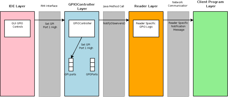
GPIO Layers: Setting GPI Port High
Component Description
- IDE Layer The IDE layer allows a user to set GPI signals to high or low. In addition it can observe GPO signals
- RMI Interface The RMI Interface is how the IDE and the Reader communicate. It exposes the functionality of a reader to the outside world
- GPIO Controller Layer As described above, the GPIO controller is the component that manages the states of the GPI and GPO ports
- Java Method Call This is the public method interface that enables the GPIO Controller to talk to the Reader specific layer (such as the LLRP or the Alien Readers).
- Reader Layer This is the reader specific (e.g. LLRP or Alien) logic that decides what happens as a result of a GPI event. For example, the LLRP reader can be set up so that a ROSpec begins executing when a GPI signal goes high.
- Network Communication Interface This is the interface between the reader and the Client program. It is reader specific. For example, with the alien reader, messages are sent in plain text. For the LLRP reader, messages are byte-encoded in specific ways. For the Awid reader, it is serial communication.
- Client Program Layer The client program is the edgeware program that controls the reader, for example TagCentric or the BEA server
Scenario Description
In the above figure, GPI port 1 is set high by a user in the IDE. The IDE then sends a message to the GPIOController via the RMI interface. The Controller sets its internal port to high and then notifies any obervers inside of the particular reader. In this case, there is an observer. The observer sends a GPI event notification message to the reader client.
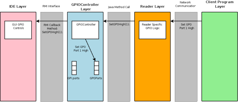
GPIO Layers: Setting GPO Port High
Component Description
See above
Scenario Description
The client program sends a message to the reader to set a GPO port high (setting a GPO port high cannot be done in the IDE, because GPO ports are output, and should only be able to be observed in the IDE). The reader-specific logic should tell the GPIOController to set a GPO port high. The GPIOController lets the IDE know that a GOP port has been changed via the IDE's callback interface (for more information see Engine RMI Interface)). Now that the IDE is aware that a GPO port has changed states, it can take appropriate action to change something in the GUI to let the user know.


