Designer User's Guide
From RifidiWiki
Contents
- 1 Requirements
- 2 Installation
- 3 Launching Rifidi Designer
- 4 Getting Started - Example Designer Simulation
- 4.1 Create Layout
- 4.2 Add a Conveyor
- 4.3 Add a Push Arm
- 4.4 Add a Gate
- 4.5 Add a Box Producer
- 4.6 Component Placement
- 4.7 Assign a Data Producer to a Producer component
- 4.8 Create a Group
- 4.9 Add Components to Group
- 4.10 Turn On Components
- 4.11 Start Simulation
- 4.12 Pause Simulation
- 4.13 Reset Simulation
- 4.14 Turn Off Components
- 4.15 Edit Simulation Layout
- 5 Layouts
- 6 Components
- 7 Placement
- 8 Layout Navigation
- 9 MiniMap
- 10 Simulation
- 11 Properties
- 12 Quickstart Video
Requirements
- Microsoft Windows 2000/XP/2003 or Linux (Ubuntu, Red Hat, SuSe)
- Sun Java Runtime Environment 1.5 (J2SE 5.0)
Installation
Designer is completely written in Java so installation is very easy. Additionally, Designer is packaged in a standard installer.
- Download the latest version of Rifidi Emulator from http://sourceforge.net/projects/rifidi/
- Double click to run the install. Follow the on screen instructions.
Launching Rifidi Designer
- Windows Users: Simply click the shortcut located in the Rifidi folder in the Start Menu/Programs folder.
- Linux Users: Double click the executable file located in the installation directory.
Getting Started - Example Designer Simulation
Create Layout
- Once the program is loaded, the main UI will be present.
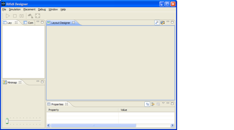 The Rifidi Designer UI
- To create a new layout, click the 'file' and 'new layout'.
- Enter in a layout name, select size of the room (64x64 or 256x256 square feet) and click 'Finish'.
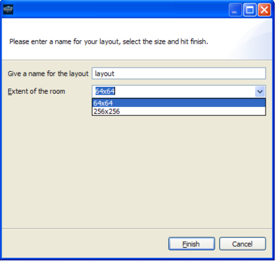 Create New Layout
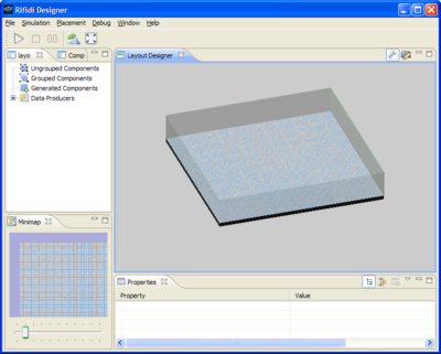
 - A new empty layout will be displayed in the UI ready for use
 New Layout


Add a Conveyor
- Click on the 'Components' Tab to view the library of all available components to add to a layout.
- If the list is not expanded already, Click on the '+' next to RFID Base Models to expand the list.
- Highlight the 'Conveyor' component and drag and drop to the 'Layout Designer'
- Enter a name for the component and the feet per second. (Example 1 ft/sec)
- You will now see the component displayed in the 'Layout Designer'. Note: For placement refer to the Component Placement Section
Add a Push Arm
- Click on the 'Components' Tab to view the library of all available components to add to a layout.
- If the list is not expanded already, Click on the '+' next to RFID Base Models to expand the list.
- Highlight the 'Push Arm' component and drag and drop to the 'Layout Designer'
- Enter a name for the component, the seconds per push and click 'Finish'. (Example: 1 sec/push)
- You will now see the component displayed in the 'Layout Designer'. Note: For placement refer to the Component Placement Section
Add a Gate
- Click on the 'Components' Tab to view the library of all available components to add to a layout.
- If the list is not expanded already, Click on the '+' next to RFID Base Models to expand the list.
- Highlight the 'Gate' component and drag and drop to the 'Layout Designer'
- Enter a name for the component, select a reader type and click 'Next'.
- Enter a name for the reader and click 'Finish'.
- You will now see the component displayed in the 'Layout Designer'. Note: For placement refer to the Component Placement Section
Add a Box Producer
- Click on the 'Components' Tab to view the library of all available components to add to a layout.
- If the list is not expanded already, Click on the '+' next to RFID Base Models to expand the list.
- Highlight the 'Producer' component and drag and drop to the 'Layout Designer'
- Enter a name for the component, seconds per box and click 'Finish'. (Example: 5 sec/box)
- You will now see the component displayed in the 'Layout Designer'. Note: For placement refer to the Component Placement Section
Component Placement
Conveyor Placement
- In the Layout Designer View, click on the conveyor. Note: Yellow arrows will show the direction of the conveyor
- Move the conveyor to the desired location by holding the left mouse button down. Note: The area below the component will be highlighted in green when placement is valid and red when placement is invalid.
- Release the left mouse button once the desired location has been reached.
- If placement is valid the component will move to the new location and if placement is invalid the component will move to the prior valid location
Box Producer Placement
Push Arm Placement
Gate Placement
Assign a Data Producer to a Producer component
Create a Group
Add Components to Group
Turn On Components
Start Simulation
Pause Simulation
Reset Simulation
Turn Off Components
Edit Simulation Layout
Move Individual Components
Rotate Individual Components
Move Group of Components
Properties
Edit Conveyor Speed
Edit Box Producer Rate
Layouts
Create Layout
- Once the program is loaded, the main UI will be present.
 The Rifidi Designer GUI
 - To create a new layout, click the 'file' and 'new layout'.
- Enter in a layout name, select size of the room (64x64 or 256x256 square feet) and click 'Finish'.
 Create New Layout
 - A new empty layout will be displayed in the UI ready for use
 New Layout


Open Layout
- Once the program is loaded, the main GUI will be present.

- To start the reader, click the 'add reader button'.
- Select the reader type to be emulated and pick the address to start the reader on. For the purposes of this quickstart guide, start an Alien Reader.
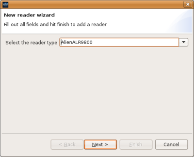 Select the kind of reader
 - Select the Reader's IP and port address. 127.0.0.1:1000, will use the loopback address of the current system and start listening on port 30000.
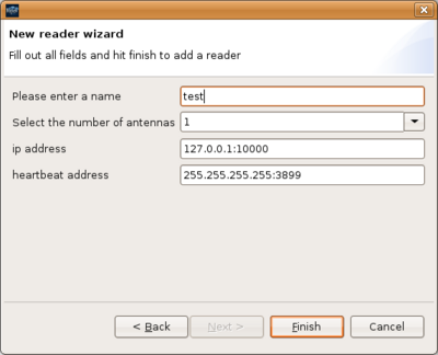 Supply the reader's IP and port
 - Right click the reader and press start
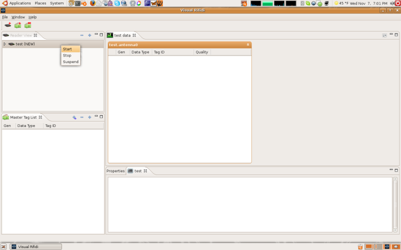 Rightclick on the reader to begin
 - The reader may be stopped at any time right clicking and pushing stop.


Components
Viewing
Adding to Layout
Turn on Components
Turn off Components
Rename Components
Delete Components
Placement
Moving Components
Rotating 90%
UnGrouped Components
Grouped Components
Create Group
Add Components
Rename Group
Delete Group
Generated Components
Data Producers
MiniMap
Zoom in/Zoom out
Simulation
Play
Pause
Reset
Properties
Quickstart Video
A video of these installation steps can be seen here: http://www.rifidi.org/rifidipackage/rif_out.html