Designer User's Guide
From RifidiWiki
Contents
- 1 Designer Deprecated
- 2 Quick Start Video
- 3 Requirements
- 4 Installation
- 5 Launching Rifidi Designer
- 6 Getting Started - Example Designer Simulation
- 6.1 Create Layout
- 6.2 Add a Conveyor
- 6.3 Add a Push Arm
- 6.4 Add a Gate
- 6.5 Add a Box Producer
- 6.6 Component Placement
- 6.7 Push Arm Instructions
- 6.8 Create a Group
- 6.9 Add Components to Group
- 6.10 Turn On Components
- 6.11 Start Simulation
- 6.12 Pause Simulation
- 6.13 Reset Simulation
- 6.14 Turn Off Components
- 6.15 Add Components to Group
- 7 Layout Navigation
- 8 MiniMap
- 9 Camera
Designer Deprecated
Rifidi Designer has been deprecated and will shortly be replaced by a new product, Rifidi Prototyper. The information on this page will remain up, and Designer may still be downloaded from the "deprecated" folder on the Rifidi Sourceforge page, however the product is no longer being supported.
Quick Start Video
A quick start video is available at http://www.rifidi.org/videos/designer/designer.swf
Requirements
- Microsoft Windows 2000/XP/2003 or Linux (Ubuntu, Red Hat, SuSe)
- Sun Java Runtime Environment > 1.6.4 (J2SE 6.0)
- IMPORTANT: does not work with earlier JRE versions.
Installation
Designer is packaged in a standard installer, which makes installation very easy.
- Download the latest version of Rifidi Emulator from http://sourceforge.net/projects/rifidi/
- Double click to run the install. Follow the on screen instructions.
Launching Rifidi Designer
- Windows Users: Simply click the shortcut located in the Rifidi folder in the Start Menu/Programs folder.
- Linux Users: Double click the executable file located in the installation directory.
Getting Started - Example Designer Simulation
Create Layout
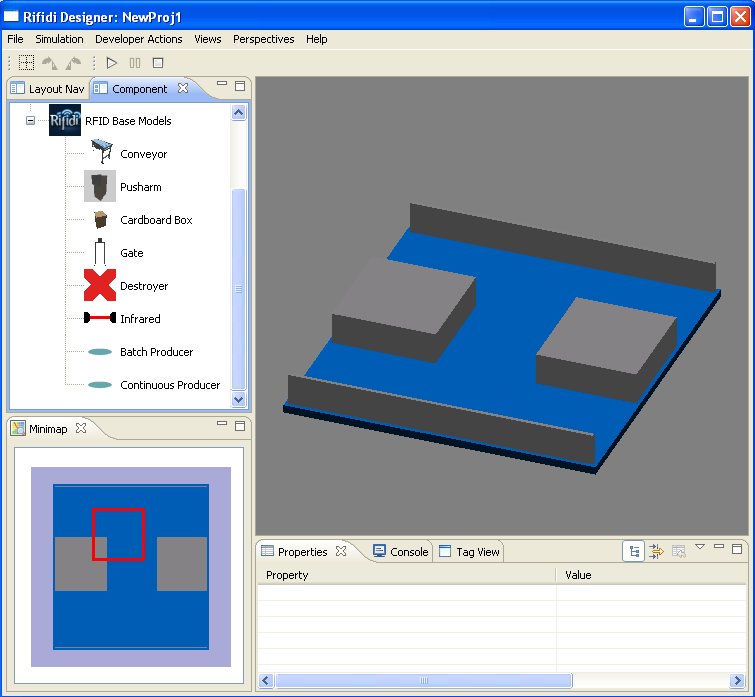
- Once the program is loaded, the main UI will be present.
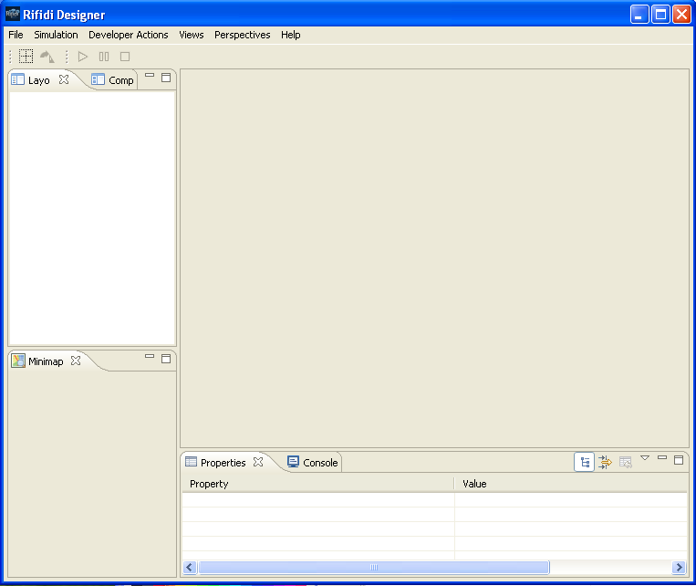 The Rifidi Designer UI
- To create a new layout, click the 'file' and 'new'.
- Select the map from the list of options which you would like to use, and give the layout a name.
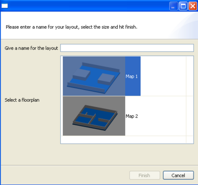 Create New Layout
 - A new empty layout will be displayed in the UI ready for use.
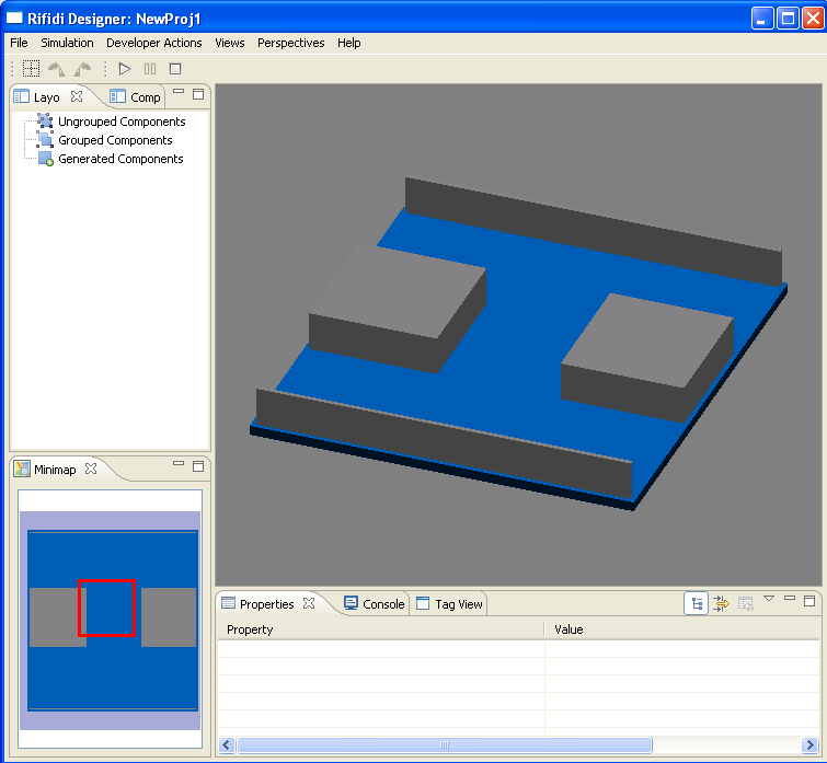 New Layout


Add a Conveyor
- Click on the 'Components' Tab to view the library of all available components to add to a layout.
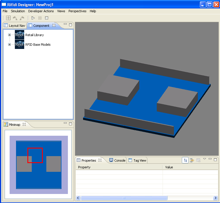 The Rifidi Designer UI
 - If the list is not expanded already, Click on the '+' next to RFID Base Models to expand the list.
 The Rifidi Designer UI
 - Highlight the 'Conveyor' component and drag and drop to the 'Layout Designer'
- The name and speed of the new component will show up in the "properties" tab at the bottom. You can change these values if you wish.
- You will now see the component displayed in the 'Layout Designer'. Note: For placement refer to the Component Placement Section


Add a Push Arm
- Click on the 'Components' Tab to view the library of all available components to add to a layout.
- If the list is not expanded already, Click on the '+' next to RFID Base Models to expand the list.
- Highlight the 'Push Arm' component and drag and drop to the 'Layout Designer'
- The name and speed of the push-arm are given in the bottom tab marked "properties". You can edit them if you wish.
- You will now see the component displayed in the 'Layout Designer'. Note: For placement refer to the Component Placement Section
- Right-click it and select Turn On to activate it
Note: See the push-arm section for instructions on how to get a push-arm working
Add a Gate
- Click on the 'Components' Tab to view the library of all available components to add to a layout.
- If the list is not expanded already, Click on the '+' next to RFID Base Models to expand the list.
- Highlight the 'Gate' component and drag and drop to the 'Layout Designer'
- Enter a name for the component, select a reader type and click 'Next'.
- Enter a name for the reader and click 'Finish'.
- You will now see the component displayed in the 'Layout Designer'. Note: For placement refer to the Component Placement Section
Add a Box Producer
- Click on the 'Components' Tab to view the library of all available components to add to a layout.
- If the list is not expanded already, Click on the '+' next to RFID Base Models to expand the list.
- Highlight one of the 'Producer' components (choose based on the type of tag you wish to produce from this producer) and drag and drop to the 'Layout Designer'
- You will now see the component displayed in the 'Layout Navigator'. Note: For placement refer to the Component Placement Section
- Create some tags by going to the "TagView" tab and clicking on the "+" at the top of the tab and creating whichever tags you like.
- Highlight and drag the tags to the producer you wish the producer to produce to the component in the "Layout Navigator" tab.
- The box producer will now produce those tags in designer when the scenario and the producer are both turned on.
Component Placement
Conveyor Placement
- In the Layout Designer View, click on the conveyor. Note: Yellow arrows will show the direction of the conveyor
- Move the conveyor to the desired location by holding the left mouse button down. Note: The area below the component will be highlighted in green when placement is valid and red when placement is invalid.
- Release the left mouse button once the desired location has been reached.
- If placement is valid the component will move to the new location and if placement is invalid the component will move to the prior valid location
Box Producer Placement
- In the Layout Designer View, click on the Box Producer.
- Move the producer to the desired location by holding the left mouse button down. Note: The area below the component will be highlighted.
- Once the producer is over the end of the conveyor, release the left mouse button to finish placement.
Push Arm Placement
- In the Layout Designer View, click on the Push Arm.
- Move the push arm to the desired location by holding the left mouse button down. Note: The area below the component will be highlighted.
- Once the push arm is next to the right end of the conveyor, release the left mouse button.
- To finalize the placement, verify the push arm is pointed in the direction to push over the conveyor (Look for shaded area to be over conveyor). If not then you can rotate the component by 90 degrees by clicking on the component and then clicking on the rotate 90 degrees button in the toolbar.
Gate Placement
- In the Layout Designer View, click on the Gate.
- Verify the space between the gate's legs can fit over the conveyor based on the conveyor's placement. If not then click on the gate and rotate 90 degrees by clicking on the 90 degree rotate button in the toolbar.
- Move the gate to the desired location by holding the left mouse button down. Note: The area below the component will be highlighted in green when placement is valid and red when placement is invalid.
- Once the gate is over the center of the conveyor, release the left mouse button.
Push Arm Instructions
Placing
Place a push arm, and place a gate with an Alien reader near the push arm. Be sure to select the "Enable GPI/O for this reader in the New Reader Wizard. It should look something like this:

GPIO
The push arm works by an Alien or LLRP (or any other reader that supports GPIO) reader sending a GPIO signal to the push arm. To connect up the GPIO, we first have to go to the GPIO perspective. Click on Perspectives -> GPIO. You should get a window that looks something like this:

In this diagram, you can see a reader, a push arm, and 2 infrared beams. GPO ports are on top, represented by the darker grey textured background. GPI ports are on the bottom represented by the lighter grey texture. For instance, the Alien reader shown has 8 GPO ports and 4 GPI ports.
- Expand the Palette if it isn't already open by pressing the arrow on the right.
- Select the "Solid Connection" button in the palette and drag an arrow it from a GPO port on the Alien reader (GPO ports are the ones on top with the dark grey background) to the GPI port on the Push Arm. This means that the Push Arm will push the next box which comes in front of it when the GPO port on the reader that you selected goes high.
- Don't forget to turn on the push arm and the gate. Other wise nothing will happen.
After that, the push arm should fire when you want it to.
For help on how to get the Alien Reader to manipulate its GPO ports, see our help guide on the subject.
Create a Group
- Click on the Layout Navigator tab.
- Right click on Grouped Components
- In the right click menu, click on create group
- In the create group wizard, enter in a group name (example: group1)
- You will now see the new group listed under Grouped Components
Add Components to Group
- Click on the Layout Navigator tab.
- Click on the '+' next to Ungrouped Components to expand the ungrouped components list if not expanded already.
- Click on the '+' next to Grouped Components to expand the grouped list if not expanded already.
- In the Ungrouped Components list, click on the conveyor component (Example: conveyor1).
- Hold the left mouse button down on the conveyor component and drag and drop into the Group (Example: group1)
- Repeat steps 2 - 4 for each or the remaining ungrouped components
- Once all the steps have been completed, you will now have all the components assigned to a group. (Example: group1) Now you can move the components around in a group in the Layout Designer instead of having to move each component seperately. There are other benefits of groups which will be described in later sections.
Turn On Components
There are two ways to turn on components:
- Click on the Layout Navigator tab if not already selected.
- Click on the '+' next to Grouped Components to expand the grouped list if not expanded already.
- Click on the '+' next to the group name (Example: group1) to expand the group if not expanded already.
- Right click on the conveyor component
- In the conveyor component right click menu, click on turn On
- Repeat steps 3-4 for each component in the group
or the short cut is to:
- Click on the Layout Navigator tab if not already selected.
- Click on the '+' next to Grouped Components to expand the grouped list if not expanded already.
- Click on the '+' next to the group name (Example: group1) to expand the group if not expanded already.
- Right click on group (Example: group1)
- In the group right click menu, click on Turn On
- This will Turn On all the components assigned to tha group
You can now connect to the virtual reader (Alien, AWID, Symbol, LLRP) you created with a client such as telnet, client library, middleware or EdgeServer.
Start Simulation
- On the Designer Toolbar, you can now click on the play button to start the simulation
- Once you start the simultaion you should now see boxes being produced and the conveyor and push arm moving at their defined rates.
- The client connected to the virtual reader should now report tags as the boxes pass through the gate's antenna.
Pause Simulation
- On the Designer Toolbar, you can now click on the Pause button to start the simultaion
- Once you pause the simultaion you should now see boxes being produced and the conveyor and push arm moving pause, left in the previous state.
- The client connected to the virtual reader will continue to be connected.
Reset Simulation
- On the Designer Toolbar, you can now click on the reset button to start the simultaion
- Once you reset the simultaion you should now see boxes being produced, the conveyor and push arm moving be reset
- The client connected to the virtual reader will continue to be connected.
Turn Off Components
There are two ways to Turn Off components:
- Click on the Layout Navigator tab if not already selected.
- Click on the '+' next to Grouped Components to expand the grouped list if not expanded already.
- Click on the '+' next to the group name (Example: group1) to expand the group if not expanded already.
- Right click on the conveyor component
- In the conveyor component right click menu, click on Turn Off
- Repeat steps 3-4 for each component in the group
or the short cut is to:
- Click on the Layout Navigator tab if not already selected.
- Click on the '+' next to Grouped Components to expand the grouped list if not expanded already.
- Click on the '+' next to the group name (Example: group1) to expand the group if not expanded already.
- Right click on group (Example: group1)
- In the group right click menu, click on Turn Off
- This will Turn Off all the components assigned to the group
The client should now disconnect from the virtual reader as if the device has been powered off
Add Components to Group
- Click on the Layout Navigator tab.
- Click on the '+' next to Grouped Components to expand the grouped list if not expanded already.
- Click on the '+' next to the group (Example: groups1) to expand the assigned grouped component list if not expanded already.
- Click on the conveyor component.
- At the bottom below the Layout Designer view you will now see the conveyor component's property view.
- Click on the speed property and change the value.
- The next time you Turn On the components (if not on already) and play the simulation you will see the new speed.
Edit Box Producer Rate
- Click on the Layout Navigator tab.
- Click on the '+' next to Grouped Components to expand the grouped list if not expanded already.
- Click on the '+' next to the group (Example: groups1) to expand the assigned grouped component list if not expanded already.
- Click on the box producer component.
- At the bottom below the Layout Designer view you will now see the box producer component's property view.
- Click on the rate property and change the value.
- The next time you Turn On the components (if not on already) and play the simulation you will see the new rate.
- The layout navigation is a tab on the left side of the Designer screen. It contains 3 collapsible lists of components:
- Grouped Components
- Ungrouped Components
- Generated Components
Ungrouped Components
- This is where all the ungrouped components are listed. Click on the plus sign to see them.
- You can also turn off and turn on all of the grouped components at the same time. To do this, right click on the "ungrouped components" and select "turn off" or "turn on".

Grouped Components
- This is where all of the grouped components are listed. Click on the plus sign to see all of the groups, and click on the plus sign on individual groups to list the components in those groups.
- You can turn on and turn off everything in a group by right clicking on the group and clicking "turn on" or "turn off".

Generated Components
- This is where you can find all of the components generated by a producer.
- You can delete these components by right clicking on them and selecting "Delete Entity".

MiniMap
The MiniMap is on the lower left of the Designer screen. If you don't see it, click on views -> Show MiniMap.

- You can navigate around the MiniMap by clicking and dragging the red box where you want to go. This will cause the overhead camera to shift where you drag it to.
- You can also simply click on the map where you want the camera to be.
Zoom in/Zoom out
- You can zoom in and zoom out by clicking on the MiniMap and moving the mouse wheel backwards and forwards.
Camera
The camera is set at a fixed angle, but it can be zoomed in and zoomed out, and it can also be moved on the MiniMap.
Zoom in/Zoom out
- You can zoom in and zoom out by clicking on the main view screen and moving the mouse wheel backwards and forwards.
[cuu du lieu]
[noithat] [Phần mềm nhân sự] [Quản lý Nhân sự] [Phần mềm quản lý nhân sự tiền lương] [tham tu] [cong ty tham tu] [thành lập doanh nghiệp] [dịch vụ kế toán] [dich vu ke toan] [ke sieu thi] [quay ke]